3.3 The timer
With our sleeves rolled up and dirt all the way up to our elbows, it’s time to grab a coffee and do so reading/studying again. In this section interrupts will be introduced through the use of a timer.
A lot of applications that are built using an Arduino need some sense of time. As mentioned earlier the ATMega has 3 dedicated timers on chip: two 8-bit timers and one 16-bit timer. Through these timers the concept of time can be implemented.
16-bit Timer
One component that is in almost every microcontroller is a Timer/counter. This timer/counter can be used for many things: stopwatch, wave generation, timing, … The block diagram of the 16-bit timer/counter in the Arduino is shown here. Next to this 16-bit timer/counter there are 2 8-bit timer/counters available. The documentation reports registers like TCNTn and OCnB. The letter n is a placeholder for the number of the timer. In the case of the micro controller on the Arduino, the 16-bit counter results in n = 1.
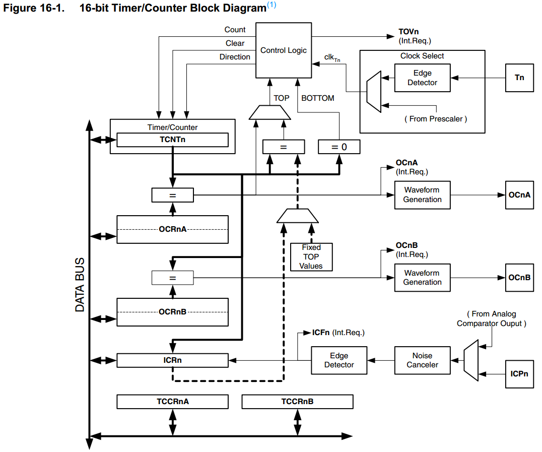
Block Diagram of the 16-bit counter in the Arduino microcontroller. Source: arduino.cc
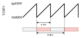
During normal operation the counter simply counts from 0x0 to its maximum value.. The left-side image below shows what happens to the 16-bit value TCNT1. The counter can also be used in a different mode: Clear-timer-on-compare (CTC). In this mode the timer starts again at 0x0000, but only counts to a certain value. When this value is reached, the counter resets and starts over. The right-side image below shows the CTC mode with the cap at 0x7FFF and at 0x3FFF.
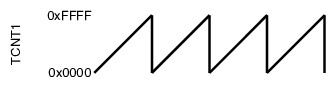
Value of TCNT during normal operation of the 16-bit counter.
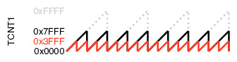
Value of TCNT during clear-timer-on-compare (CTC) operation of the 16-bit counter.
The value to which the timer counts in CTC mode can be set through the register OCR1A: the Output Compare Register of timer 1 named A. As can be seen in the block diagram, there is a comparator in the Timer block that compares TCNT1 and OCR1A. The result of this comparator can be evaluated in the control logic. By configuring the timer this control logic can be altered.
What is the frequency at which the counter reaches its maximum value in normal mode ?
Timer frequency
To determine the frequency at which the counter operates a quick visit to the datasheet holds the answer. The clkT1 can be generated from an external or internal clock source: clkI/O. This incoming clock goes through a prescaler which can be set by the Clock Select bits (CS12, CS11, and CS10).
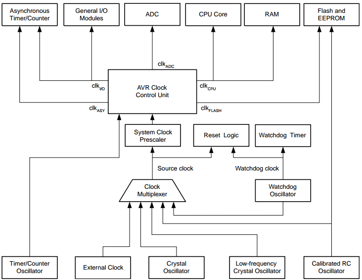
Clock Distribution (source: Datasheet)
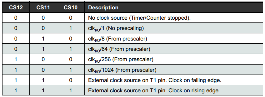
Clock Select bits for prescaler cconfiguration (source: Datasheet)
To introduce a clock, a crystal oscillator is used. The one on the Arduino UNO board runs at a frequency of 16'000'000 Hz or 16 MHz. This is the frequency at which the CPU is working, often referred to as the clock speed. Given that frequency, and the value of the pre-scaler, the clock frequency at which the counter operates can be calculated.
\( f_{clk_{T1}} = { f_{clk_{I/O}} \over prescaler_{T1}} = { 16e6 \over 2^{10}} = 15'625 Hz \)
Because the counter needs 216 clock ticks to reach its maximum, this maximum will be reached every \( 2^{16} \over 15625 \) = 4.19 s. If a LED were to be toggled every time the counter reaches its maximum, the frequency of the toggling LED would be (2 * 4.19 s)-1 = 0.119 Hz.
Value of TCNT during clear-timer-on-compare (CTC) operation of the 16-bit counter.
Polling vs Interrupt
Before you put down your coffee to get back to work let’s discuss polling first. A nice illustration of polling is shown below.
Our toddler is polling her father. Another example of polling is shown below. This clip, however, ends with an interrupt.
Would it not be nice that the CPU could just continue working on something else until a certain event occurs eg. the timer reaching its maximum value ? In the second example (the one with the cartoon), the co-pilot interrupts what the processor was doing.
An interrupt is a signal that goes to the processor signalling a certain event. There are two sources for this interrupt: hardware and software. The timer that reaches his maximum count and signals this to the processor is an example of a hardware interrupt. An example for a software interrupt could be an attempt of a division by zero.
Configuring the timer with interrupts
As can be seen from the block diagram on the top of this page, 4 registers are available for interaction with the software:
- TCNTn: Timer/counter value for counter n
- OCRnA/OCRn: Output Compare Register A for counter n (also available for B)
- ICRn: Input Capture Register
- TCCRnA: Timer/Counter Control Register for counter n
The first three registers (TCNT, OCRA/OCRB, and ICR) are all 16-bit registers. Their functionality is self-explanatory. The Control Register needs more explanation, though. Luckily for us, there is … the datasheet.
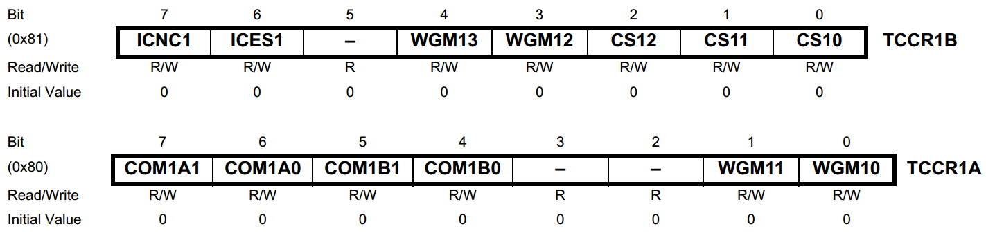
Timer/Counter Configuration Register 1 (TCCR1)
The following configuration are given. For other configuration the reader is invited to consult the datasheet for him/herself.
- CS12 | CS11 | CS10 : Clock Select as explained above. Dividing the incoming clock with a 1024-bit prescaler gives configuration: 101.
- WGM13 | WGM12 | WGM11 | WGM10 : Waveform Generation Mode. This is the formal name for the normal mode or the CTC mode that were discussed above. Normal mode of operation is achieved by setting these bits to: 0000
- IC.. : Input Capture (Noise Cancellation and Edge Select) are irrelevant for this mode of operation and can be both set to: 0
- COM1.. : What should happen when OCRA or OCRB can be chosen from 4 different options (hence the 2 bits). Both these settings are irrelevant for this mode of operation and can be both set to: 00
In summary, TCCR1A should be set to 0b00000000 (or 0x00) and TCCR1B should be set to 0b00000101 (or 0x05).
The settings above configure TIMER/COUNTER 1 to operate like requested, but the interrupts still have to be set. To set this, two different flags need to be enabled. In the final section of this chapter these two flags are elaborated on. For now, it suffices to know there is a general Interrupt Enable and a ‘maskable’ Interrupt Enable. The former can be set by calling the function sie() the latter should be set through a register: Timer Interrupt Mask Register (TIMSK1).
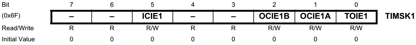
Timer Interrupt Mask Register (TIMSK1)
As can be seen from the image above, there are other Interrupts that can be set. For this example only the final one (Timer Overflow Interrupt Enable) should be set to one. This results in setting TIMSK1 to 0b00000001 (or 0x01).
Finally, when the interrupt is triggered, something should happen. Otherwise this would be quite useless. When an interrupt occurs, the processor halts whatever it was doing and executes a function. In stead of “calling” the function ourselves, this function call is done automatically. To be able to distinguish between different interrupt sources, different prefixed function names are available. The next section of this chapter will elaborate on this as well. The function-name that is linked to the TIMER/COUNTER 1 overflowing is: TIMER1_OVF_vect.
The example code below puts everything together.
#define LED_1Hz 7

int led0_status = 0;

ISR(TIMER1_OVF_vect) {
  if(led0_status == 1) {
    led0_status = 0;
    digitalWrite(LED_1Hz, LOW);
  } else {
    led0_status = 1;
    digitalWrite(LED_1Hz, HIGH);
  }
}

void setup()
{
  pinMode(LED_1Hz, OUTPUT);

  /* configure TIMER/COUNTER 1 */
  TCCR1A = 0x00;
  TCCR1B = 0x05;

  /* enable interrupt mask */
  TIMSK1 = 0x01;

  /* enable the interrupts */
  sei();
}

void loop() {

}
Compile and run the code above. What is the frequency at which the LED toggles ?