3.2: Arduino multi frequencies
Time to make some harmonics.

image source: wikipedia.org
Three’s a charm
The example below has to be completed. Three LEDs are placed and defined. If you run the code, the left-most LED starts blinking at 1 Hz. You can choose how you want approach this. Either you search for you very own Arduino and rebuild the design. Or, otherwise, you can use a (webbased) simulator like for example Tinkercad.
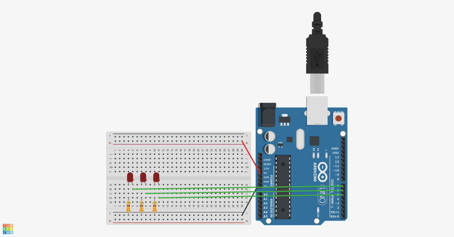
#define LED_1Hz 7
#define LED_2Hz 6
#define LED_3Hz 5

void setup()
{
  pinMode(LED_1Hz, OUTPUT);
  pinMode(LED_2Hz, OUTPUT);
  pinMode(LED_3Hz, OUTPUT);
}

void loop()
{
  digitalWrite(LED_1Hz, HIGH);
  delay(500);
  digitalWrite(LED_1Hz, LOW);
  delay(500);
}
Complete the example so the three LEDs blink at 1 Hz, 2 Hz, and 3 Hz, respectively.
Something to point out is the preciseness of the LEDs. If you’d hold a high-speed camera on the setup and do some precise timing, it becomes clear that the frequencies are not very precise. Take the example of 1 Hz. Executing the digitalWrite() function is not instantaneous. As you’ll learn in this course, executing a function involves some steps which are overhead. Nonetheless, if lives were at stake, this could be measured very precisely. The additional overhead time could be reduced from the 500 ms, to achieve a better precision.
Making a second ‘application’
A second application that can be run on the Arduino is a Serial port echo service. You know this is a killer-app and could make you millions ;-)
Make a program that can read in a character from the Serial port. The Arduino should simply echo the incoming byte in HEX.
Merge the two applications
The third exercise is simple, at least on paper screen it is.
Merge both programs.
What is effect of the additional application on the preciseness of the blinking LEDs' frequency ?