3.1 Arduino UNO
The Arduino UNO is an open-source microcontroller board. It is powered by an off-the-shelf ATMega microcontroller from Microchip . The datasheet for this family of microcontrollers can be found here .

An Arduino UNO. Source. arduino.cc
This datasheet contains a block diagram of the AVR architecture. Nonetheless, most of these components could be found in many other microcontrollers as well. The image should be familiar to students that took up the Elektronische systemen course at KU Leuven. 😄

Block diagram of the AVR Architecture. Source. podkalicki.com
The ATMega microcontroller on the Arduino has, amonst other components, a dedicated Timer. This timer block consists out of 3 timers: two 8-bit timers and a single 16-bit timer. Through the use of the 16-bit timer, the concept of interrupts is illustrated.
Low Level programming
Programming the Arduino UNO can be easily done with the Arduino IDE. This user friendly environment is a very nice entry point for new users of microcontrollers. Future engineers, however, should be able to understand what is going on behind the curtain. After all, magic doesn’t exist.
The Arduino IDE
Bit manipulations
When bare metal programming a microcontroller it is often required to start poking specific bits in a register. A quick background refresh is given first.
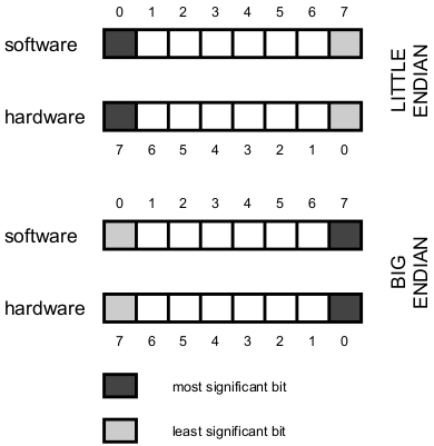
Endianness and approaches in hardware and software
Binary
Everybody agrees that the hexadecimal number 0x41 is binary written as 01000001. This is interpreted as 1 x 26 + 1 x 20 = 64 + 1 = 65. The least-significant bit is in the term: 1 x 20.Endianness
When this byte is serialised (eg. in an array or in communcation) the question of "Which bit do we write first ?" arises. This is defined as the endianness. Big Endian writes the MSB on the right, while Little Endian writes the LSB on the right.Hardware vs. Software
In contrast with the software world, hardware engineers typically start counting from the right (instead of the left). The C code for the assignement above would be:int myvalue[] = {1, 0, 0, 0, 0, 0, 1, 0}; where in VHDL this assignment would be:
myvalue <= "01000001";
Now both 'worlds' see myvalue[0] as '1'.
Let’s explore the bit manipulations. First we assign the value 1 to an 8-bit type variable.
  unsigned char x;
  x = 1;
With this line, x holds the number “00000001”. This means the bytes are represented in Little Endian.
Setting the sixth bit, might be a bit cumbersome. First the result of 25 has to be calculated. After googling the result, the programmer can write:
  unsigned char x;
  x = 32;
More seasoned C programmers might be inclined to use the shift operator : «. This litteraly takes te value 1 (remember: this is represented as 00000001) and shifts this value 5 positions to the left, while inserting 0’s on the right ( 00000001 + 00000 => 00000 + 00100000 => 00100000).
  unsigned char x;
  x = (1 << 5);
Next to the shift operator, bitwise operators are also heavily used for setting and/or clearing certain bits. The logical functions AND (&), OR(|) and NOT(~) can be used as efficient tools for bit fiddling.
❗ ❗ 🐉 Beware of the dragons 🐉 ❗ ❗.
  unsigned char x=0, y=0;
  ...
  x = (1 << 5);
  y = y | (1 << 5);
  ...
  x = (1 << 5);
  y = (1 << 4);
  if(x && y) { printf("YES\n"); } else { printf("NO\n"); }
  if(x & y)  { printf("YES\n"); } else { printf("NO\n"); }
  if(x | y)  { printf("YES\n"); } else { printf("NO\n"); }
- What will be the printed output of the C-code above ?
- Write a line of C-code that:
- sets the 3rd bit to '1' and all others to '0' (resulting in "00000100")
- sets the 4th and 5th bit to '1' and all others to '0(resulting in "00011000")'
Hello hardware, this is software speaking
A frequently used way of communication between hardware and software is through memory-mapped registers. Such a register can be read or written by software at a certain address. This register serves as driver (in the hardware sense) for inputs of a specific hardware component.
When a register is written by software and read by (or driving) hardware, such a register is sometimes called a command register (CR). When a register is written (or driven) by hardware and read by the software, such a register is sometimes referred to with a status register (SR).
Going through the datasheet of the microcontroller on the Arduino many CRs can be found. Section 36 summarises these registers on more than 3 pages. An example of a register that serves both as a CR and as a SR for controlling of the Analog-to-Digital Converter is shown below. As can be learned from the datasheet, the MSB of this register is used to enable or disable the hardware ADC through software instructions.
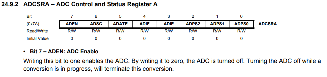
Example of a CR in the ATMega microcontroller. Source: arduino.cc
The register above can be accessed from software on address register 0x7A. When the software writes to this register ALL 8 bits are written. This is important to remember to avoid one of the dragons described above.