Hello world
Let’s put the introduction to a pause and look at some code !!
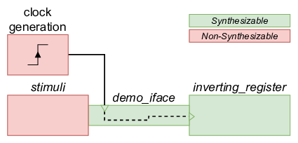
The example below shows a very simple test. The DUT only performs an inversion of the 8 incoming bits, when the data valid is high. The inverted result is stored in a register which is routed to the output of the DUT.
The image below shows the architecture that is constructed for the example.
Life will become more complicated (very soon), but for now the example is stored in a single file.
/***
 * The interface
 ***/
interface demo_iface ( input logic clock );
  logic [7:0] data_in;
  logic data_valid;
  logic [7:0] data_out;
endinterface

/***
 * The DUT
 ***/
module inverting_register(demo_iface di);
  always @(posedge di.clock)
  begin
    if(di.data_valid)
      di.data_out <= ~di.data_in;
  end
endmodule


/***
 * Test environment
 ***/
module Top;
  logic clock=0;

  // clock generation - 100 MHz
  always #5 clock = ~clock;

  // instantiate an interface
  demo_iface theInterface (
    .clock(clock)
  );

  // instantiate the DUT and connect it to the interface
  inverting_register dut (
    .di(theInterface)
  );

  // provide stimuli
  initial begin
    theInterface.data_in <= 8'h0;
    theInterface.data_valid <= 1'b0;
    repeat (10) @(posedge clock);

    theInterface.data_in <= 8'h12;
    theInterface.data_valid <= 1'b1;
    @(posedge clock);
    theInterface.data_valid <= 1'b0;
    @(posedge clock);

    theInterface.data_in <= 8'h55;
    theInterface.data_valid <= 1'b1;
    @(posedge clock);
    theInterface.data_valid <= 1'b0;
    @(posedge clock);

    repeat (1000) @(posedge clock);
    $finish;
  end

endmodule
Interface
First the interface is defined. There are 3 signals, two of which are 8-bit buses. Also, there is an incoming clock which is declared.
DUT
The DUT itself is very simple. The register, with a chip enable, acts upon a rising edge of the clock.
Note that the ports of the component are declared through the interface.
Top
Finally, the Top module:
- generates a clock,
- instantiates an interface,
- connects the interface to the DUT,
- and, provides stimuli
Simulating the code above, produces a waveform as can be seen in the image below.
