Turn up the colours
The LEDs are nice, but not very festive. As the PYNQ Z2 board also has RBG LEDs, we can turn up the colours.
RGB LEDs
The RGB LEDs on the PYNQ Z2 have three inputs that can be driven by the FPGA. Although driving a single input gives a single colour, different colours can be shown.
Look at all the colours
Instead of driving a single input, multiple inputs can be driven as well. In contrast with colour mixing with paint (which works subtractive) colour mixing with light works additive.
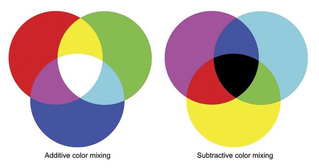
Additive vs Subtractive colour mixing
If you add all the different colours of light, you end up with white light. If you add all the different colours of paint, you get a mess black.
As an example: driving both the red and green inputs, will turn the RGB LED yellow.
More colours
Next to driving each colour, and driving multiple colours simultaneously, tweaking the duty cycle also changes the colour. Off course this only holds when multiple colours are driven.

Example of colour mixing changes in simulation
PROTIP Notice that the red signal is the inverted blue signal !!
When you simulate for a longer period, you will no longer see the details of the changing duty cycle, but you will see the effect on the RGB LEDs. The example below shows that after red and green are both driven, only red is burning. Thereafter, blue joins the show.

Example of colour mixing changes in simulation
Light intensity
The RGB LEDs are very bright. The intensity could be altered by, again, changing the duty cycle. First construct the three signals that will drive the LED, than apply a final duty cycle change before it goes to the output.

Example of duty-cycle changes in simulation
Mapping
Off course the driving outputs of the designed component need to be connect to the RGB inputs. As you might have guessed by now, this is where the .xdc comes in. Depending on whether you have a single output vector, or three distinct outputs per LED, your .xdc should contains some section that looks like the example below.
##RGB LEDs
set_property -dict { PACKAGE_PIN L15   IOSTANDARD LVCMOS33 } [get_ports { RGB0[0] }]; #IO_L22N_T3_AD7N_35 Sch=led4_b
set_property -dict { PACKAGE_PIN G17   IOSTANDARD LVCMOS33 } [get_ports { RGB0[1] }]; #IO_L16P_T2_35 Sch=led4_g
set_property -dict { PACKAGE_PIN N15   IOSTANDARD LVCMOS33 } [get_ports { RGB0[2] }]; #IO_L21P_T3_DQS_AD14P_35 Sch=led4_r

set_property -dict { PACKAGE_PIN G14   IOSTANDARD LVCMOS33 } [get_ports { RGB1_blue }]; #IO_0_35 Sch=led5_b
set_property -dict { PACKAGE_PIN L14   IOSTANDARD LVCMOS33 } [get_ports { RGB1_green }]; #IO_L22P_T3_AD7P_35 Sch=led5_g
set_property -dict { PACKAGE_PIN M15   IOSTANDARD LVCMOS33 } [get_ports { RGB1_red }]; #IO_L23N_T3_35 Sch=led5_r
Exercises
Exercise 6
For this exercise you will have to make a hardware design that drives one of the RGB LEDs. Six colours should be shown in a loop: the 3 primary colours and the 3 secondary colours.
Exercise 7
For this exercise you will have to make a hardware design that drives one of the RGB LEDs. Twelve colours should be shown in a loop: the 3 primary colours, the 3 secondary colours and the six colours in between.